WeChat:
+86 13871525936
Views: 325 Author: Anna Publish Time: 2024-08-01 Origin: Site
The optical module operates at the physical layer of the OSI model and is a crucial component of fiber optic communication. Its primary function is to implement the conversion between optical and electrical signals. The key performance indicators of the optical module can be measured from two aspects: the transmitting end and the receiving end.
Key performance indicators of the transmitting end include: average output optical power, extinction ratio, and central wavelength of the optical signal.
The average output optical power refers to the optical power emitted by the light source at the transmitting end of the optical module under normal operating conditions, representing the intensity of the light. In communication, we typically express optical power in dBm. The output power is related to the proportion of "1"s in the transmitted data signal; the more "1"s, the greater the optical power. The transmitting optical power is a critical parameter affecting the transmission distance of the optical module.
Methods to detect the optical module's output power include: reading DDM information from a switch, eye pattern testing, spectrum testing, and using optical power meters.
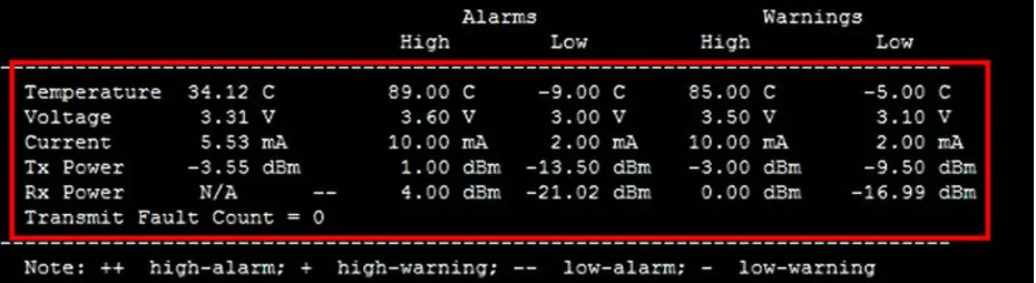
In the diagram, you can see Alarms and Warnings. The warning alert is a level one alarm, while the alarm indicates a warning/pre-warning range, classified as a level two alarm. Generally, if it exceeds level one, it may still be usable, but the bit error rate will increase. If it exceeds level two, the optical module will become unusable, so operating within the level one range is considered normal.
In the diagram, the optical module's output power is -3.55 dBm, which falls within the warning range of -3 dBm to -9.5 dBm, indicating normal data transmission.
The extinction ratio is an important parameter for measuring the quality of the optical module. It refers to the minimum ratio of the average optical power emitted during full "1" modulation to the average optical power emitted during full "0" modulation, expressed in dB. The extinction ratio can be seen as a measure of the efficiency of the laser operation. A higher extinction ratio does not necessarily mean a better optical module; rather, an optical module that meets the 802.3 standards is considered good. The typical minimum range for the extinction ratio is from 8.2 dB to 10 dB.
The commonly used central wavelengths for optical modules include three main bands: 850 nm, 1310 nm, and 1550 nm. Optical fiber loss typically decreases with increasing wavelength. The loss is lower at 850 nm, increases between 900 nm and 1300 nm, decreases again at 1310 nm, and is lowest at 1550 nm, with losses increasing beyond 1650 nm. Thus, 850 nm is considered the short-wavelength window, while 1310 nm and 1550 nm are regarded as long-wavelength windows.
Receiving End of the Optical Module
Key performance indicators of the receiving end include: overload optical power, receiver sensitivity, and received optical power.
Overload Optical Power
Also known as saturation optical power, this refers to the maximum average input optical power that the receiving component of the optical module can handle under specific bit error rate conditions, measured in dBm.
It is important to note that under strong light conditions, the photodetector may experience current saturation, requiring time to recover, during which sensitivity decreases, potentially leading to bit errors. In simple terms, exceeding this overload optical power could damage the equipment, so it is advisable to avoid strong light exposure during operation.
Receiver Sensitivity
Receiver sensitivity refers to the minimum average input optical power that the receiving component can detect under specific bit error rate conditions, measured in dBm. While the output power refers to the transmitted light intensity, receiver sensitivity indicates the light intensity the optical module can detect. Generally, the higher the data rate, the worse the receiver sensitivity, meaning the minimum detectable optical power increases, thus placing higher demands on the receiving components.
Received Optical Power
Received optical power is the average optical power that the receiving component can receive under specific bit error rate conditions, measured in dBm. The upper limit is the overload optical power, and the lower limit is the receiver sensitivity.
In summary, if the received optical power is below the receiver sensitivity, it may fail to receive the signal due to insufficient power. Conversely, if the received optical power exceeds the overload optical power, it may also fail to receive the signal due to bit errors.For more information, please visit YXFiber.


